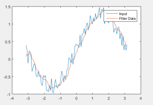
You can also specify 'allfir' to design using all available methods, in which case the function returns a cell array of System objects. MATLAB contains commands for various analog filter designs. Plot the gain and phase frequency responses on the the left and the right graphs respectively. Design the filters with the design function using the desired method from the list above. To plot the results on a semilog scale where the y-axis is linear and the x-axis is. First, load the desired filter specification: frequencies to the vector F, and the complex response values to the vector H. In this first example, we compare several FIR design methods to model the magnitude and phase of a complex RF bandpass filter. For more information about FIR and IIR design algorithms, see. Once a specification object has been created, you can design an FIR or an IIR filter using the design function. What's the problem matlab filter signal-processing.
#PLOT FILTER DESIGNER OUTPUT MATLAB HOW TO#
The example also shows how to smooth the levels of a clock signal while preserving the. Pass the above signal through the bandpass. Keep high frequency twice the low frequency. Below are the steps to be followed: Define the sampling rate. but the values in the vector output are all infinite. This example shows how to use moving average filters and resampling to isolate the effect of periodic components of the time of day on hourly temperature readings, as well as remove unwanted line noise from an open-loop voltage measurement. In the above 2 examples, we used a three-channel signal, in this example, we will use a 2-channel signal and will pass it through a Bandpass filter. output zeros (1,61) for k1:61 output output + coeff (k) dirac (61-k) end. I thought about using this code: I have 61 coefficients.

In DSP System Toolbox™, you can create a filter specification object with a desired frequency response using fdesign.arbmagnphase. I have an array with all the FIR filter coefficients ak, now I need to plot the impulse response. Set Quantization Parameters provides access to the properties of the quantizers that compose a quantized filter. In mostĬases, the response specification is comprised of a frequencies vector F = of N increasing frequencies, and a frequency responses vector H = corresponding to the filter's complex response values. Use the buttons on the sidebar to configure the design area to use various tools in the filter designer app.


Custom magnitude and phase filter specifications are similar, but also include phase response, usually as a complex value encoding both gain and phase response. Frequency Response Specification and Filter Designįilter responses are usually specified by frequency intervals (bands) along with the desired gain on each band.


 0 kommentar(er)
